Back to IF2224 Teori Bahasa Formal dan Otomata
Path Logic for Input A
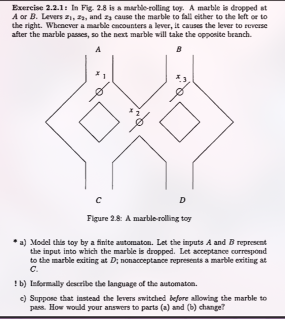
When a marble is dropped in A, it first encounters lever x1.
ASCII Flowchart for Input A
      [Input A]
          |
         (x1)
        /    \
(State 0)    (State 1)
      /          \
    (x2)          (x3)
   /    \        /    \
(0)      (1)    (0)      (1)
 /        \    /        \
C          D  D          C
Step-by-Step Breakdown for Input A:
-
First Decision at
x1:-
If
x1is 0 (Left): The marble follows the left path and goes to leverx2.-
Second Decision at
x2:-
If
x2is 0 (Left): The marble exits at C. -
If
x2is 1 (Right): The marble exits at D.
-
-
Levers Flipped:
x1andx2.
-
-
If
x1is 1 (Right): The marble follows the right path and goes to leverx3.-
Second Decision at
x3:-
If
x3is 0 (Left): The marble exits at D. -
If
x3is 1 (Right): The marble exits at C.
-
-
Levers Flipped:
x1andx3.
-
-
Path Logic for Input B
When a marble is dropped in B, it first encounters lever x3.
ASCII Flowchart for Input B
      [Input B]
          |
         (x3)
        /    \
(State 0)    (State 1)
      /          \
    (x2)          (x1)
   /    \        /    \
(0)      (1)    (0)      (1)
 /        \    /        \
D          C  C          D
Step-by-Step Breakdown for Input B:
-
First Decision at
x3:-
If
x3is 0 (Left): The marble follows the left path and goes to leverx2.-
Second Decision at
x2:-
If
x2is 0 (Left): The marble exits at D. -
If
x2is 1 (Right): The marble exits at C.
-
-
Levers Flipped:
x3andx2.
-
-
If
x3is 1 (Right): The marble follows the right path and goes to leverx1.-
Second Decision at
x1:-
If
x1is 0 (Left): The marble exits at C. -
If
x1is 1 (Right): The marble exits at D.
-
-
Levers Flipped:
x3andx1.
-
-
a) Finite Automaton Model
The toy can be modeled as a finite automaton. The state of the system is determined by the orientation of the three levers x1, x2, x3. We’ll represent the left position as 0 and the right position as 1.
-
States (Q): A 3-bit string
(x1, x2, x3). There are 2³ = 8 possible states.Q = {000, 001, 010, 011, 100, 101, 110, 111}
-
Input Alphabet (Σ): The two drop points for the marble.
Σ = {A, B}
-
Start State (q₀): Assuming all levers start pointing left.
q₀ = 000
-
Transition (δ) and Output (λ) Functions: The core of the automaton is its transition function
δ(state, input) -> next_stateand its output functionλ(state, input) -> output. A marble pass flips the levers it encounters. “Acceptance” is defined as the marble exiting atD.
The complete behavior is described in the table below:
| Current State (q) | Input | Path Taken | Levers Flipped | Exit (λ) | Next State (δ) | Accepts? |
|---|---|---|---|---|---|---|
| 000 | A | A → x1(L) → x2(L) | x1, x2 | C | 110 | No |
| 000 | B | B → x3(L) → x2(L) | x3, x2 | D | 011 | Yes |
| 001 | A | A → x1(L) → x2(L) | x1, x2 | C | 111 | No |
| 001 | B | B → x3(R) → x1(L) | x3, x1 | C | 100 | No |
| 010 | A | A → x1(L) → x2(R) | x1, x2 | D | 100 | Yes |
| 010 | B | B → x3(L) → x2(R) | x3, x2 | C | 001 | No |
| 011 | A | A → x1(L) → x2(R) | x1, x2 | D | 101 | Yes |
| 011 | B | B → x3(R) → x1(L) | x3, x1 | C | 110 | No |
| 100 | A | A → x1(R) → x3(L) | x1, x3 | D | 001 | Yes |
| 100 | B | B → x3(L) → x2(L) | x3, x2 | D | 111 | Yes |
| 101 | A | A → x1(R) → x3(R) | x1, x3 | C | 000 | No |
| 101 | B | B → x3(R) → x1(L) | x3, x1 | C | 000 | No |
| 110 | A | A → x1(R) → x3(L) | x1, x3 | D | 011 | Yes |
| 110 | B | B → x3(L) → x2(R) | x3, x2 | C | 101 | No |
| 111 | A | A → x1(R) → x3(R) | x1, x3 | C | 010 | No |
| 111 | B | B → x3(R) → x1(R) | x3, x1 | D | 010 | Yes |
b) Informal Language Description
The language accepted by this automaton is the set of all sequences of marble drops (strings of ‘A’s and ‘B’s) where the final marble exits at port D.
An interesting property is that any input (A or B) always flips exactly two levers. This means the parity (even or odd) of the sum of the lever states (x1 + x2 + x3) never changes. Since we started in state 000 (an even sum), the machine can only ever be in states where the sum of the bits is even: {000, 011, 101, 110}.
So, the language can be described more precisely: It is the set of input strings w that end in a symbol (A or B) which causes an exit at D from the state the machine was in after processing the prefix of w.
c) Levers Switch Before Marble Passes
If the levers switch state before the marble passes, the logic for determining the path and the next state changes fundamentally. The path is now determined by the lever’s new position.
- New Part (a): The states, alphabet, and start state are the same, but the transition and output functions are now different, as shown in the table below.
| Current State (q) | Input | Logic | Exit (λ) | Next State (δ) |
|---|---|---|---|---|
| 000 | A | x1 flips to 1, path R → x3 flips to 1, exit C | C | 101 |
| 000 | B | x3 flips to 1, path R → x1 flips to 1, exit D | D | 101 |
| 001 | A | x1 flips to 1, path R → x3 flips to 0, exit D | D | 100 |
| 001 | B | x3 flips to 0, path L → x2 flips to 1, exit C | C | 010 |
| 010 | A | x1 flips to 1, path R → x3 flips to 1, exit C | C | 111 |
| 010 | B | x3 flips to 1, path R → x1 flips to 1, exit D | D | 111 |
| 011 | A | x1 flips to 1, path R → x3 flips to 0, exit D | D | 110 |
| 011 | B | x3 flips to 0, path L → x2 flips to 0, exit D | D | 000 |
| 100 | A | x1 flips to 0, path L → x2 flips to 1, exit D | D | 010 |
| 100 | B | x3 flips to 1, path R → x1 flips to 0, exit C | C | 001 |
| 101 | A | x1 flips to 0, path L → x2 flips to 1, exit D | D | 011 |
| 101 | B | x3 flips to 0, path L → x2 flips to 1, exit C | C | 110 |
| 110 | A | x1 flips to 0, path L → x2 flips to 0, exit C | C | 000 |
| 110 | B | x3 flips to 1, path R → x1 flips to 0, exit C | C | 011 |
| 111 | A | x1 flips to 0, path L → x2 flips to 0, exit C | C | 001 |
| 111 | B | x3 flips to 0, path L → x2 flips to 0, exit D | D | 100 |
- New Part (b): The language changes entirely. The parity property still holds (every input flips two levers), but the conditions for exiting at
Dare now different, creating a new language based on the new state transitions.